|
Home
History
Environmental Threat
Site Characterization
Man. Gas Processes
Plant Wastes
Contamination Threat Modes
Residuals - Components
Sources of MGP Liquid Effluent
FMG Plants in the US
Parallel MG Technologies
Think you've found a gas works?
Locating and Confirming a Site
Locations of US Gas Plants
FMGP In The News
FMGP In The Arts
Coal-tar Site Litigation
Related sites on the Internet
Literature of Manufactured Gas
Hatheway Harangues
Publications by Dr. Hatheway
Slide Shows by Dr. Hatheway
Slide Shows by others
Hatheway Bio
Hatheway Resume
Legal Considerations
|
|

Gas Plant Components
Inherent in locating the various "hot spots" of gas manufacturing residuals is a personal need for the remediation team to understand the basic requirements for gas manufacture. This table highlights the typical steps in a generic sense, irrespective of the particular nature of the gas process(s) actually employed at a single FMGP. It is helpful to recognize that there were several streams of wastes; 1) Tars, as separated from the process water; 2) Process water, containing smaller quantities of tars, along with other particulate wastes; and 3) Solid wastes removed by the clarification (tar removal) and purification (sulfur removal) processes, as well as the lampblack generated by the carburetted water gas and oil-gas processes and captured in wash boxes.
|
|
Generic Sequence Of Gas Manufacture (click on image to enlarge)
|
Generic Manufactured Gas Processes
Gas can be manufactured literally from any organic material. Beyond the basic unpatentable coal-gas retort design there were many variations in the design of gas-making devices or "machines." These all were subject to the patent protection systems of North America and Europe and many variations were developed for the purpose of securing separate patents. Of the many possibilities, coal, light-oil tars, and petroleum oils dominated the feedstocks and coke, a by-product of coal-gas generation, provided the basis for the carburetted water gas process of T.S.C. Lowe, as well as the patent-competing generic oil-enriched water gas processes. The author estimates that more than 500 separate patented gas-making processes actually were utilized in North America and Europe, as well as exported around the world.
|
Generic Manufactured Gas Processes
|
| Process & First Use |
General Purpose |
Waste-Stream Pollutants |
| 1805: Coal Gas Horizontal Retort Inclined Retort Vertical Retort |
Illuminating gas @ > 450 Btu, generally at the power of 14-18candles (candle power = cp). |
Coke most valuable by-product; used for Water-Gas; Tars highest quality & urban-marketable; CN; ammoniacal liquors as main tar-bearing pollutant. |
| ca. 1815: Light-Oil Gas Town Gas Institutional Gas Machines Mansions & Estates |
Used for illumination, Relatively high candle power and Btu value. |
Lampblack, tar and the various polycyclical aromatic compounds. |
| 1854: Water Gas (Blue = Producer Gas) At Individual Factories, Mines, and Mills |
Fuel gas, devoid of essential gas lighting qualities > 450 Btu/cf. Great use from 1890 to 1940s; Few tens of thousands of such plants |
Reduced unit amounts of tar and ammoniacal liquors; but often large quantities generated. |
| ca. 1860: Oil-Enriched Water Gas Town Gas Institutional Gas Machines Mansions & Estates |
Dual use, for illumination and fuel; Some sold as compressed gas in rural areas. |
Enrichment led to additional tars at the gas plant. |
| Thompson system of gas lighting for railroad trains1857: Approximate introduction#9; 9; |
Rectangular water-sealed gas holder 216 cf carried on tender of the locomotive. Alternatively, a gas holder of twice the size carried in the guards van |
Parsons, 1947, p. 123; Residuals not yet identified by the author. |
| Carburetted Water Gas (CWG) 1875: Proven and patented by T.S.C. Lowe; Rights sold to United Gas Improvement Co. (UGI) in 1884. Other manufacturers appeared after expiration of Lowe patents, about 1892. |
Coke as original-specification feedstock Anthracite as alternative feedstock Bituminous coal as undesirable alternative feedstock Sub-bituminous coal as highly undesirable feedstock. |
Labor-saving, high capacity illuiminosity enriched with light oils for greatest brilliance. As feedstock quality decreased from the ideal coke, to all manner of coal, valueless tar-water emulsions became the major, site-dumped waste. |
Oil-Enriched Water Gas 1878-1912
Numerous patents and vendors |
Eventually phased out in favor of CWG due to price increases of feedstock lights oils otherwise being used as motor vehicle fuel. |
Often represented by Brown's Directory entries as "Water Gas "without reference to Lowe process |
| Pintsch Oil Gas (Railway Yards) 1883: Introduced in U.S. as compressed gas tanks on cars |
Railway lighting for coaches, dining, baggage and mail cars |
Lampblacks and tars, at major (division) railroad yards across individual rail systems. |
| Crude-Oil Gas 1889: Pacific Coast 1925: East Coast |
Lighting and heating; Residues vary by patented process and quality of oils. |
Typified by lampblack sorbed with PAHs and related toxics. Progressive companies in west made and sold fuel briquettes. |
| ca. 1890: Coke-Oven Gas Merchant coke works Utility coke works By-product coke works Most steel mills |
Gas is the main by-product Company sells to steel industry Gas company sells coke; Uses gas Uses gas, sells coke & by-product Use both coke and gas. |
Ammoniacal liquors as process wastes and also from coke quenching; Heavy volumes of tars produced. |
| 1890: Acetylene Gas; Rural use in homes, military posts and institutions. |
High-illumination; Usually generated at site of use: Some railway usage. |
Sludge, directly from generator. |
Compiled by Allen W. Hatheway
 |
|
William Murdock's Independent Gas Supplier (Birmingham, England, 1805)
William Murdock, the Scotsman-father of manufactured gas had constructed the first commercial manufactured gas plant, at Smethwick, Soho District, West Birmingham, England by 1805. This was some seven years before the first accorded commercial gas plant, that of the Chartered London Gas Light & Coke Works went into production at London. This view shows the original gas works, yet preserved at the Soho Foundry of Boulton & Watt, Murdockąs employers and builders of steam engines and small gas works, probably about 1890. Courtesy of British Ordnance Surveys.
|
 |
|
William Murdock's Smethwick Gas Works (Smethwick, England, c.1901)
Murdock's pioneer Smethwick Gas Works is shown on this 1901 British Ordnance planimetric map of Smethwick (as the smallest of the circles denotes the gas holder at the Soho Foundry, formerly owned by Boulton & Watt. To the immediate west is the Smethwick Corporation (Town/Municipal) Gas Works, now derelict, but yet with its own ca. 1890 multilift gas holder. Gas coal was delivered via the adjacent canal. The gas holder is visible from the adjacent street and constitutes one of the more than 1000 FMGPs admitted as to ownership by British Gas PLC, the privatized remains of the 1949 Labour Government's nationalized gas industry. The figure of 1000 is believed to be a significant under-estimate of the quasi-private gas holdings of FMGPs, now undergoing an extremely simplified transfer of contaminated land to redevelopment (Courtesy, British Ordnance Surveys).
|
 |
|
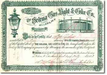
Gas Company Investment Opportunities (certificate from Helena, Montana)
From their beginning in the United States, at Baltimore, Maryland, in 1816, manufactured gas companies were locally owned, generally the brainchild of a group of several leading citizens, organized under some type of charter, originally that of the State Legislature, but giving over to "franchises" issued by the city or town. Stock was sold to raise the $25,000 or $30,000 required to purchase the gas making equipment and to hire a journeyman plumber to erect the works. About six months were required and the journeyman often stayed on the become the Gas Works Superintendent. This was the case at Burlington, Iowa, when Master Plumber Spellman stayed on, with his grown daughter Laura marrying itinerant fuel-oil salesman John D. Rockefeller. On her death, in 1915, Laura Spellman Rockefeller was proudly announced by the Burlington Hawkeye as "Richest Woman on Earth Dies, Native of Burlington."
|
Generic Layout Considerations
In the course of planning for site and waste characterization of a former manufactured gas plant, it is necessary to define the plant layout and to search for and discover each of the elements of the gas-making, storage and distribution process. This table lists the components necessary to create the gas, to cleanse (clarify) it of tar, to purify it of sulfur and other impurities, to route the gas between components, and, finally, to store it for distribution. Leaks and spillages of residuals often occurred between the physical locations of the components.
|
Generic Layout Considerations for an 1883 U.S. Coal-Gas Plant
|
| Consideration |
Feature |
Rationale |
| Construction |
Fireproof |
Make the works as nearly fireproof as possible; Steel-frames for brick buildings, roofs of iron, tin or slate. |
| Water Supply |
Abundant |
To be used for process water in the condensation train. |
| Retorts |
Benches |
Prefers lengths of 9 ft instead of 8 ft (Hyde) at least 24 inches wide |
| Risers (Bridge Pipes) |
Takes Gas to Hydraulic Main |
Should be straight, without curves |
| Furnaces |
Heating Retort Benches |
Regenerative furnaces now available and should be utilized as state of the art; Gas house coke serves better than coal; Charge directly from the retort floor. |
| Boiler |
Motive Power & Portable Heat |
Served to power engines, open and close valves, heat pipes, gas holder cups and, if present, a tar-collection railroad tank car. |
| Stacks |
Smoke from Furnaces, Retorts and Boilers |
Allocate one stack per four benches (Hyde); Extend height to a few feet above retort house ridge ventilator; Also serves to remove heat and also "deleterious gases of the furnaces." |
| Hydraulic Main |
Seals Gas Flow |
Also begins to remove tars from raw gas. |
| Tar Extractor |
First Removal |
First passage of gas beyond the Hydraulic Main; Extractor should operate on frictional removal, not by cooling (Hyde). |
| Exhauster |
Draws Gas Through System & Improves Gas Yield at Retorts |
Hyde prefers to place Exhauster as second component past Hydraulic Main; Operate by steam and install a gas governor; duplicate exhausters and engine power desirable to guard against accidents, especially those related to small fissures in the retorts. Opinion and need varies as to relative plant location. |
| Relief Holder |
Optional Use of First-Older Secondary Holder |
Often became the incidental receptacle of raw gas, taking advantage of the presence of its basin waters to cool or chill the incoming gas before pulling such off for condensation and further cleansing and purification. |
| Condenser |
Cools gas & drops as much tar as is possible |
Preferred is the multi-tubular water-cooled condenser; Gas moves through tubes set in cooling water bath; Should be set parallel so that alternative passage can be achieved during maintenance (Hyde). |
| Thermometers |
Guide to Maintaining Cooling Function |
Placed so as to monitor gas temperature in flow between components of the tar particle-removal (clarification) train; Means of judging need to adjust temperature to suit optimal removal of impurities. |
| Tar Well |
Subsurface Collection and Holding Vessel |
Collects ammoniacal liquors from condensers and subsequent particle-cleansing devices. |
| Scrubber or Washer |
Remove naphtaline all Remaining Ammonia |
Numerous patented devices; Generic layout has two cylindrical scrubbers of about 30-35 ft high and filled with hardwood slats or brush; brush being cheaper (Hyde). Spray the interior of 1st scrubber with ammoniacal liquor recovered from cooling and tar-precipitation in the tar well. Allocate once-through water purification flows of 1.25 gal/1000 cf gas to be passed, in order to adequately remove ammonia. |
| Purifier Boxes |
Remove fine particles and unwanted CO2 gas |
Hyde favors "small" purifiers, 10 x 16 feet; Construct on need, in accordance with measured purity of gas exiting the boxes; Choice of slaked (white) lime, wood shavings or sawdust, and iron oxide. Some plants use all three, placed in layers, or mixed, on wooden trays. |
| Gasometers (Gas Holders) |
Storage of cleansed gas |
Foundation conditions govern; If ground soft or of "quicksand", then consider sheet-piling a trench in which to construct the pit/basin/tank wall and also to facilitate excavation of center. Include interior drains for inward seepage, carried outside the holder pit, to a pump sump; Vent the drain pipe on the outside in event of failure of sump pumps, as to avoid hydrostatic uplift of the tank bottom. |
| Gas Holder House |
Protection of holder in cold climates |
Framework should be of iron, walls of iron, roof of slate |
| Gas Yard Pipes |
Access for cleaning |
Insure that all gas-yard pipes are fitted with accessible blind plates for cleaning of tar and/or naphthalene obstructions (Hyde). |
| Station Meter |
Final Accountability of Gas Produced |
Generally housed in the managers office, adjacent to the External entrance to the grounds; Provides basis for estimation of percentage loss of gas through distribution system. |
| Governor |
Control Over Gas Distributed |
Control pressure of distribution. |
Compiled by the author, largely from "The Management of Small Gas Works", a series by C. J. Russell Humphreys, Consulting Gas Engineer, AG-LJ, 1883, and "The Construction and Management of Gas Works, by G. A. Hyde, Cleveland, Ohio.
|
|
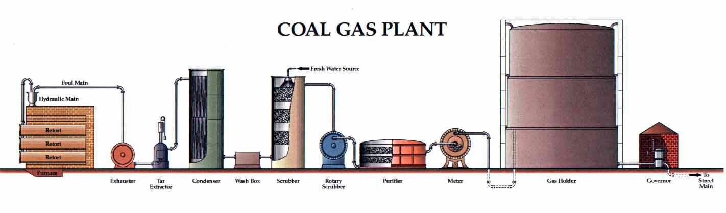
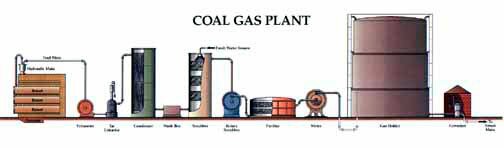
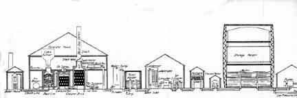
Coal Gas Plant Linear View
A composite linear view of a small to medium-size town coal gas plant in a typical circa 1900 configuration. The gas generation, clarification, purification, metering, storage and distribution sequence begins on the right, with one bench of six or nine closed-end retorts. A 400-pound charge of gas coal is loaded into each of the retorts, on a time-staggered basis and heated for four to six hours from the furnace below the bench. As gas is generated it rises up the vertical riser pipes and bubbles through a tar bath in the horizontal main, then into the horizontal foul main and moves under a slight negative pressure, created by the Exhauster, to and through the Tar Extractor, to the Multi-tube Condenser and through its bottom water bath (to separate out more tar), then through a cool-water Wash Box, and then rises upward through the fresh, cool water of the Fresh Water Scrubber and its wood shavings and out and into the Rotary Scrubber. As the gas passes through the Washer, the overall process of Clarification is complete, as directed to removal of tiny particles of tar. The process yields Ammoniacal Liquor as the aqueous phase and tar and tar sludge as the viscous liquid phase, both effluent streams are hereby separated from the gas. At the Purifier, the gas continues in processing with removal of sulfur, cyanide, heavy metal, and mm or tar, then passes through the Station Meter for a close measure of the volume of gas actually produced at the plant. Passing into the post-1900 Gas Holder, we note that there is no subsurface Tank and that purpose is served by the cool-water resting in the first (lower-ring) tank-segment of the holder. The remaining rings represent a two-lift Bell or Cup in which each lift slides up and down along the Guide Rails and a gas-seal is provided by a horizontal seal of water at the juncture of each of the two upper rings and between the lower rim of the lower lift and the upper rim of the above-ground Tank. Once in the Gas Holder the Gas is under the gravity-induced pressure of the weight of the riveted steel-plate Cup and is then pressured reduced for street distribution by the Governor and admitted to the Street Main for its entry to the Distribution System, (Artwork by Robin Snyder, Gas Works Illustrator; ) (click on the image for a larger version of this image).
|
|
|
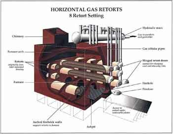
Coal-Gas Retort Bench
Coal-gas Retorts were made in the general configuration shown, and, after about 1880 generally came as a solid ceramic tube of a Dee cross-section as a measure to avoid stress-prevalent sharp corners. Retorts experienced thermal damage from the typical four-to-six hour charge cycles and commonly needed replacement within months to two years. Most plant sites will be found somewhat littered with broken retort fragments and bricks stripped from aged Bench housings, the which provided the heat-conserving support structure and the by-pass flues to heat the retorts in the absence of oxygen. Riser Pipes are here labeled Gas Off take Pipes. This is a Bench of Eights, more common to the United Kingdom, and sharing a single Furnace. Furnaces were fed by coal, by coke raked from the retorts on completion of each gas run, and sometimes supplemented by flowing tar recovered at various points in the Clarification Process. It is best not to assume that plant tar residuals were consumed in any degree unless backed by reliable plant or company records (Artwork by Robin Snyder, Gas Works Illustrator; ) (click on the image for a larger version of this image).
|
 |
|
Brown's Directory of American Gas Companies (1900)
|
|
|
Carburetted Water Gas Plant (Post-1900)
This outstanding method of gas-manufacturing was invented by T.S.C. Lowe, one of America's truly outstanding engineering geniuses. This process diagram begins on the left, with the three cylindrical Generator units of the system, developed and patented in 1875, to utilize coke as a reactor bed in the Generator, with steam injected, from the Boiler, into the Generator, then passed to the Carburetor for injection of light petroleum oils (for gas light illumination) and then into the Superheater, where more checker-board fire bricks retained heat to flash the composite gas into a fixed nature, followed by a Wash Box seal to pass the raw gas through a Tar Separator, and Scrubber, then into the Relief Holder (serving a pressure-equalization role far different from the Relief Holder of coal-gas plants). From this position the gas went on to experience a Condenser, an Exhauster, another Tar Extractor, and, finally, the purifier boxes, then the Station Meter and a Storage Holder identical for what was required at coal-gas plants. In fact, make use of this illustration for superior details to those shown for the coal-gas plant. A single three-unit Generator Set, of three cylinders, could make much more gas per day than could coal-gas benches, in addition, saving on labor and operating space in the Generator House. One major flaw came into being as coke became scarce after 1910 and, at the same time, motor vehicle fuel sales crowded the usual light gas oils off the market and CWG plants were forced to substitute coals as inferior reactor feedstock and to carburet with inferior heavier-weight oils. On the West Coast, the situation grew worse earlier, forcing the use of crude oils and the production of equally inferior tar-water emulsions as well as lampblack (soot). Generally speaking coal-gas tar carried less than 4-6 percent water, while CWG tar-water emulsions reach as much as 90 percent water. Buyers of tar-water emulsions were nearly non-existent and huge amounts of this non-salable wastes were consigned to the environment as a management option by many plant operators. Today their presence should be expected as hazardous wastes.
|
|
|
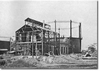
Carburetted Water Gas Plant, Paducah, Kentucky (ca. 1925)
By the early 1900s, the standard brick manufactured gas plant had given way to a steel-framed brick-facade generator building of slightly taller nature, to accommodate the usual two-story layout of carburetted water gas. This plant, built on contract by the Stone & Webster Engineering Corporation (SWEC; Founded 1889, at Boston, Massachusetts, and owners, builders, and operators of many manufactured gas plants and yet in business as a subsidiary of The Shaw Companies), has the typical operator's floor above, with the bases of the generator set cylinders extending upward from the ground floor. The traditional monitor-style factor roof ridge is a preferred holdover from 19th century architectural tradition and promotes ventilation on hot days. A newer above-ground gas holder lies to the right rear and an obviously older gas holder is seen to the left, probably serving as the relief holder to buffer the pressure waves associated with moving from blow cycle to run cycle, every few minutes. (Photo from undated SWEC sales brochure of ca. 1925).
|
 |
|
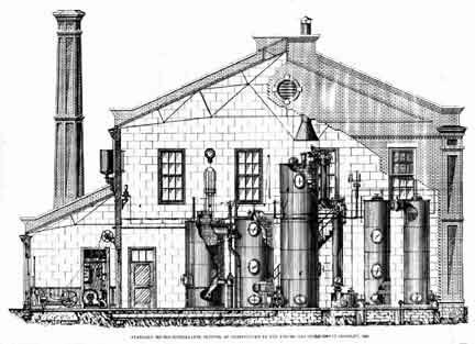
U.G.I. 1890 Version Of T.S.C. Lowe's Carburetted Water Gas Plant T.S.C.
Lowe sold his basic carburetted water gas patents to the United Gas Improvement Company, of Philadelphia, in 1884, just two years after its founding. Lowe shortly moved west, to Pasadena, California, and became a leading civic, gas manufacturing personality, and developer of public attractions in Southern California. His base patents began to expire about 1892 and CWG units began to appear as marketed by other than U.G.I., notably the Gas Machinery Company (Cleveland), Bartlett-Hayward Company (Baltimore), Gas Engineering Co. (Trenton), Western Gas Construction Co. (Ft. Wayne, IN), Koppers Co. (Pittsburgh), and West Gas Improvement Co., of Britain. The term "water gas" was used loosely throughout the gas era, even in Brown's Directory of North American Gas Companies, and should be question-factored into site and waste characterization studies. This view, from an 1890 U.G.I. sales brochure portrays a single Generator Set of, from left to right, Generator, Carburetor, and Double Superheater, followed, on the right, by the Wash Box and two cylindrical Scrubber towers. Separated tar wastes were plumbed to transfer below the floor of this two story gas house. Note that there is a typical factory-type smoke stack at the boiler, with the blow-fume cylindrical chimney above the superheater shell.
|
|
|
Combination Coal-Gas And Carburetted Water Gas Plant (ca. 1925)
As noted above, an ideal combinational mix of gas manufacturing equipment was to generate gas and coke via coal-gas machines and to employ the coke for general plant heating of boilers and gas-making furnaces, then to employ the coke also as the reactor bed for the carburetted water gas generator sets. This design, by Stone & Webster, at Pawtucket, Rhode Island shows the related layout (Photo from an undated SWEC sales brochure of ca. 1925).
|
 |
|
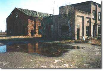
Hancock (Ripley), Michigan
Ruins of the FMGP at Hancock (Ripley), Michigan, a plant built for coal-gas generation and expanded to include carburetted water gas (CWG). There was a certain symbiosis in this dual operational capacity, in the years after widespread availability of CWG equipment (from the United Gas Improvement Company, of Philadelphia, purchasers of T.S.C. Lowe's patents in 1884) and before 1910, when coke produced at the coal-gas plant could be used to fire the plant boilers, to fire the furnace below the retort benches, and to serve as the feedstock-reactant bed of the CWG sets.
|
 |
|
Loomis Gas Producer (From Miller, 1910)
Gas Producers make up the forgotten bulk of American coal-tar sites. This technology produced "Blue" Water Gas, that is fuel gas made from coke or nearly any other organic matter, to thermally disassociate superheated steam into hydrogen gas (H2) and carbon monoxide (CO), both combustible at low Btu and without illumination qualities. The technology was suggested in Belgium in 1832 and pioneered in Britain in the 1850s by Sir William Siemens and perfected about 1861. Producer gas truly came into its own, in the U.S. about 1890 and continued in force until supplanted here and there by newly-arriving natural gas, mainly after 1930 and through 1960. Plants were installed in all manner of factories, in nearly every industry, especially those requiring heat. Factory owners bought the machines directly from manufacturers and operated them with plant personnel. Tars were generated and clarified and normally the waste waters and their tars were handled by options chosen by the factory management. There were hundreds of manufacturers across the nation. Patents were dodged in many ways, leading to the proliferation of designs. Shown is a Loomis Gas Producer, one of the leading varieties, as produced by the Loomis-Pettibone Company of New York City, NY.
"Bituminous coal contains a large amount of tarry vapors formed by the hydrocarbons, which condense on coming into contact with cold surfaces, and if these are drawn through an incandescent bed they add still further to the combustible ... If the tar cannot be so treated, it must be washed out of the gas together with the dust, water vapor, and the uncombined carbon dioxide." J.B. Rathbun, Consulting Gas Engineer, Chicago, IL, in Gas Engine Troubles and Installation, 1911.
|
|
|
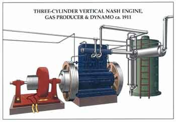
Producer Gas Engine
(Nash, Three-Cylinder Variety, ca. 1911)
Producer gas engines were the preferred power transfer medium for producer gas, here shown, in the center of the view (blue color), as driving an electric-generating D.C. dynamo (red color) and powered directly from the adjacent gas producer (green color). Normally, the entire gas producer set would be equipped with a condensing and washing tar removal device, with tar-bearing effluent sent through the floor and into some form of waste transport channel or sewer (Artwork by Ms. Robin Snyder, Gas Works Illustrator; [email protected]).
|
|
|
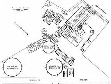
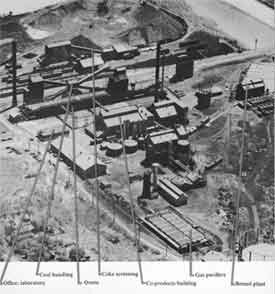
Coke Works, St. Louis, Missouri 1950
Calital low oblique aerial photograph of the Laclede Gas Light & Coke Company utility byproduct coke plant at Carondelet District of South St. Louis, Missouri. This configuration was the result of some modifications to the 1914 plant, built as an economic investment just prior to the start of World War I, in Europe. The entire site today measures about 16 ha. and lies at the juncture of the Mississippi River (top view) and the River des Peres, a major stormwater channel (shown to the right) of St. Louis. The site is geologically complex and contains karst features, an open tar pond, and an 1872-1905 coal-gas plant (not shown, but lying at the extreme west edge, beyond the lower edge of this view, along Broadway Blvd). The plant was abandoned by its third owner in 1987 and is the property of the St. Louis Community Redevelopment Authority and under a VCP order to its original builder. Historic activities that have gone on at this site include the first European settlement west of the Mississippi River (Tamaroa, 1700-1703; portions of riverboat Captain James B. Eads' Union Army gunboat works (1862-1865) , Carondelet Gas Light Company (1872-1905), the world-class Vulcan Steel Mill (1870-1888) and Balloon Training School V of the United States Army Signal Corps (1917-1918).
|
|
|
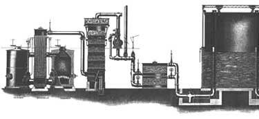
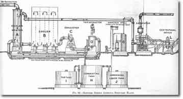
Koppers Direct Ammonia Recovery Plant (Post-1910)
Heinrich Koppers, a premier German gas engineer, emigrated to the United States in 1908 and enjoyed a brief but spectacular career in design of by-product coke ovens before his return to his native country in 1914, as a victim of the outbreak of the great European war. He sold his prosperous engineering company to Pittsburgh financiers headed by J.P. Morgan. The Koppers name became the leader in coke by-product plant design and much of the ongoing research in technologies for ever more efficient production of manufactured gas and of coal-tar by-products. The firm expanded into all aspects of the coal-tar chemical industry and provided the basis technology for production of synthetic rubber under the terrifying early days of World War II, with the loss of Asia to the Japanese. The Koppers firm eventually bankrupted under pressure of its numerous environmental remediation obligations. Shown is a late Koppers plant design for direct recovery of ammonia from a by-product coke-oven plant (click on the image for a larger version of this scanned image).
|
|
 Visitors Visitors
|
|